 |
|
|

|
|
How to choose what is right for your needs: Below we’ve summarized some of the main items that should be taken into consideration when buying an optical comparator. Please feel free to contact us with any questions regarding sales, applications, or competitive products. Step 1 – Is a horizontal or vertical light path model best for your application? Horizontal light path Optical Comparators have a beam of light traveling horizontally across a work stage. This is the most common and versatile style of comparator and comprises more then 95% of comparator inspection applications. The horizontal beam is well suited for large and small parts and the work stage can accommodate a wide variety of work-holding tooling. Typical applications include milled or turned components, screw machine parts, plastic injection molded parts, threads, grooves, extrusions, large heavy parts and shafts to be held on V blocks or between centers. J&L Metrologies line of optical comparators can be configured to operate manually or under full CNC control. They can also be fitted with a video camera system to operate in tandem with the projection optics when configured as a Vivic Measurement System Vertical light path Optical Comparators have a beam of light traveling vertically. Parts being inspected are placed on a plate of glass that the light beam travels through. Vertical comparators are ideal for flat parts like gaskets, O rings, stamped parts and electronics. Many of these components can also be inspected using our Vivic series Vision Systems (video camera based). J&L Metrology’s line of vertical comparators and Vivic Vision Systems can be configured to operate manually or under full motorized CNC control. Manual systems feature quick release mechanisms on both axes for rapid travel. Back to Top Step 2 – What screen size and stage size best suits your application? Standard J&L screen sizes are 10”, 14”, 20”, 30” and 50” but we can also offer special models with a screen size range between 6” to 120”. Before choosing a screen size, determine how much of the part REALLY must be viewed at one time. When using a digital readout system it is not necessary to view the entire part to measure it. Calculations can be made by dividing the screen diameter by the lens magnification. For example using 10X lens on a 14" optical comparator would enable viewing 1.4" of the part on the screen 14"/10=1.4". Verify that the work stage size, travel and weight capacity will accommodate all of the parts that are intended to be inspected. Back to Top How large of a viewing screen should you get? How big is big enough? The answer is based on the type of measurements you plan to make. Measurement by comparison (with overlay charts or screen templates) can use the entire viewing screen. A larger screen means you can see more of the part at any one time, perhaps measuring many features at once with the same chart. Measurement by motion (with visual alignment or edge detection) uses the movement of the worktable assembly and screen rotation to measure the part. How large of a part you can measure is based solely on the overall travel of the worktable. If you need to use overlay charts, for thread or form measurement for example, then a larger screen may be needed depending on the size of the parts. The table below shows the field-of-view (how much can be seen at one time) for some common screen sizes and magnification levels. For other combinations, simply divide the screen size by the lens magnification. Back to Top Field Of View
Step 3 – What lens/lenses you will require? Follow the chart below to decide what lens will match the tolerances required. A basic rule of thumb is that a typical attentive operator can repeatedly discriminate .004” on the comparator screen. Dividing the “discernible resolution” by the lens magnification determines the minimum resolution attainable for each lens. Back to Top Step 4 – Do I need a digital readout? Select a basic XY digital readout if only positions and distances are required. If measurement of circles, angles, and parametric distance is required, then select a readout with geometric capability. Repetitive part measurement may encourage the selection of a CNC capable readout. Automatic edge sensing should be considered to eliminate operator subjectivity and increase repeatability and accuracy. Back to Top Step 5 – What options or tooling will be required for my Optical Comparator? Repeatability and accuracy will suffer if the work piece is not properly and securely held. Work-holding is just as important when inspecting a component as when machining the component. Careful consideration should be given to tooling and to the surface on which you place your comparator. J&L offers a very wide range of standard work-holding solutions and our applications engineers will be happy to work with you to develop special work-holding as required. See our separate brochure for options. Optical comparators come in an wide variety of shapes and sizes. Benchtop, floor model, in-line, side-screen, front screen, side-table. How do you know what type of system to get, and which options to specify? If you have questions – we have answers, Contact our sales team to We have arranged this on-line selection guide to help you through this decision making process. If you have any questions, feel free to e-mail our staff for Back to Top assistance. Benchtop or Floor Model? Whether you choose a benchtop or floor model comparator may ultimately depend on the size and weight of the parts to be measured. Other factors to consider include space (floor models typically take up more space than benchtop systems), required screen size (benchtop systems rarely have screens larger than 14" or 16"), and cost (floor models are generally more expensive). What kind of parts are being measured? Benchtop models are smaller, lighter, and have lower load carrying capacity and measuring range than most floor model systems. Consequently, one usually finds benchtop comparators employed for measurement of small, lightweight parts such as plastic moldings, stampings, lathe work, etc. Floor models, on the other hand, offer substantial load capacity and large travel, and are often used to measure large machined castings, dies, and heavy tooling. The following table gives some idea of the relative capacities of J&L METROLOGY benchtop and floor model comparators. Back to Top Objective Lenses / Optics The optics are the heart of any comparator. When you think about it, the lenses in a comparator are really gages. Why? Because it is the image they form that is measured, not the part itself. And to make sure the image is accurate, optical quality (in design and manufacture) is critical. You will find several different types of optics offered on optical comparators. Regardless of the type, however, the optics must be free of distortion (magnification change across the image), produce a flat field (image over the entire screen is in sharp focus), and have excellent resolution (sharpness of the image). Let us take a look at each type and discuss the relative merits of each. Back to Top Objective Lenses / Optics Simple Reversed Optical System – As used on J&L CLASSIC series instruments
Simple Reversed Optical System – As used on J&L ICON series instruments
Fully Corrected Optics – As used on J&L EPIC series instruments
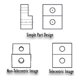
Telecentricity The closer an object is to you, the larger it appears. This is one of the fundamental principles of optics. The same is true for any optical system, whether your eye, a camera, or an optical comparator. But this can cause an error when measuring a three dimensional part, or if the image is simply a little bit out of focus. Why? Because adjusting the focus on a non-telecentric, simple optics system changes the distance between the part and the optics, and that changes the magnification. The effect is not that large (typically several thousandths of an inch measured at the part), but in today’s world of ever shrinking tolerances, you need to be as precise as you can. Telecentric relay lens optics were developed by J&L METROLOGY and Eastman Kodak in 1945 to alleviate this problem. Here is a good example that shows the difference between non-telecentric and telecentric optics: A simple part, with a step and two through holes machined into it, will appear "in perspective" to a non-telecentric system, as shown below (the effect is exaggerated for clarity). The machined step on the top (which is farther away from the optics) looks smaller. A telecentric system will create an image free from this effect, with no measurable difference in magnification. Back to Top Benefits
All J&L METROLOGY optical comparators feature true telecentric optical systems. Some manufacturers claim "telecentric illumination" but you owe it to yourself to verify the benefits of such a system. Only an optical system designed from the start as telecentric delivers the advantages stated above. Back to Top
|


© 2011 J&L Metrology, Inc. – Springfield, VT USA. All Rights Reserved
Web Site Designed by William Mahony Designs